Close
All Categories
    Filters
    Preferences
    Search

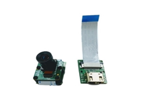
    Herelink Airunit V1.1 PCBA

    The Herelink Air Unit V1.1 PCB (PCBA) is the core internal circuitry of the updated HD video transmission system from CubePilot. It features several hardware improvements over the original V1.0 to support expanded peripheral connectivity and more stable performance.

    MFR Part #: 299-00040
    $625.01
    Key Hardware Features of V1.1 PCB
    • Ethernet Port: A dedicated Ethernet interface is now available on the board to support additional peripheral devices and data streaming options.
    • SD Card Slot: An integrated microSD card slot has been added for onboard recording or data storage.
    • Processing Power: Features an integrated 8-core SOC (PineSync technology based on the S1 processor) for custom application development and high-speed data computing.
    • Video Handling: Includes a 4-core Mali-T860 GPU for powerful video image analysis and low-latency transmission. 
    Technical Specifications
    • Input Voltage: Recommended ~7V; range 6V – 12.6V (supports 3S LiPo). Avoid sharing a BEC with servos to prevent power noise.
    • Power Consumption: Average consumption is less than 4W.
    • Physical Interfaces:
      • 2x Micro HDMI: Supports 720p/1080p at 30/60fps.
      • UART: 3.3V / 5V level for MAVLink telemetry.
      • S.bus: Two 3.3V RC outputs.
      • Micro USB: For debugging and firmware upgrades via OTG mode.
      • Antenna Connectors: 2x MMCX for 2.4GHz signal transmission. 
    • Operation & Troubleshooting
      • Pairing: Hold the "Pair/Reset" button for ~3 seconds until LED2 blinks to initiate binding with the ground station.
      • Firmware: Use the latest flasher_win application for updates. Note that firmware for V1.1 and V1.0 may differ.
      • DIP Switches: On V1.1 hardware, the switch positions for special modes (like Air-to-Air) are often reversed compared to V1.0 documentation (e.g., Switch 1 Down, 2 Up). 


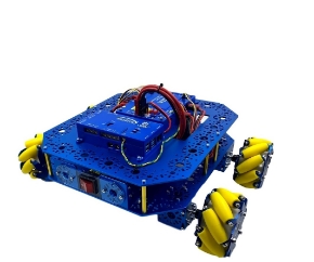
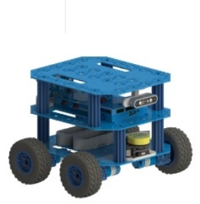
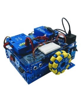
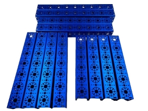
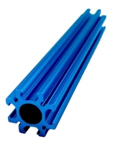
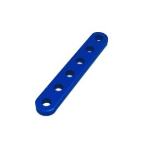
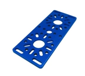
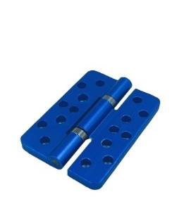
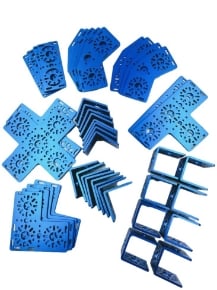
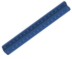
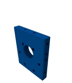
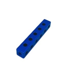
    STEM BOT Pro Kit - Parts List

    (Download to View STEM BOT Parts List as PDF)

    Note: 3D CAD files for all parts are available at www.studica.com/studica-robotics-resources

    Controllers included in the STEM BOT Pro Kit:

    • VMX Robotics Controller 
      • The Studica Robotics VMX Robotics Controller can be used an a Robot Control System or Vision/Motion processor, supporting Java and C++.  The controller integrates the navX-IMU, Gigabit Ethernet, USB3.0 ports and built-in Wifi and Bluetooth.
      • Highly-integrated, inexpensive, WiFi-enabled, multi-core Linux computing platform with lots of USB IO for expansion.
      • 32-bit ARM Microcontroller incorporating sophisticated I/O and digital communications engines
      • Low-cost MEMs Inertial Measurement Units (IMUs)
      • Powerful software providing rich libraries and tools for developing robot control software in C++, Java
      • CAN bus for high-speed, real-time communication between devices
    • Titan Quad Motor Controller 
      • The Studica Robotics Titan Quad Motor Controller is a powerful, 4-channel CAN-based motor controller with a built-in fuse-box (for DC motors up to 20A).

    Key Hardware Features of V1.1 PCB
    • Ethernet Port: A dedicated Ethernet interface is now available on the board to support additional peripheral devices and data streaming options.
    • SD Card Slot: An integrated microSD card slot has been added for onboard recording or data storage.
    • Processing Power: Features an integrated 8-core SOC (PineSync technology based on the S1 processor) for custom application development and high-speed data computing.
    • Video Handling: Includes a 4-core Mali-T860 GPU for powerful video image analysis and low-latency transmission. 
    Technical Specifications
    • Input Voltage: Recommended ~7V; range 6V – 12.6V (supports 3S LiPo). Avoid sharing a BEC with servos to prevent power noise.
    • Power Consumption: Average consumption is less than 4W.
    • Physical Interfaces:
      • 2x Micro HDMI: Supports 720p/1080p at 30/60fps.
      • UART: 3.3V / 5V level for MAVLink telemetry.
      • S.bus: Two 3.3V RC outputs.
      • Micro USB: For debugging and firmware upgrades via OTG mode.
      • Antenna Connectors: 2x MMCX for 2.4GHz signal transmission. 
    • Operation & Troubleshooting
      • Pairing: Hold the "Pair/Reset" button for ~3 seconds until LED2 blinks to initiate binding with the ground station.
      • Firmware: Use the latest flasher_win application for updates. Note that firmware for V1.1 and V1.0 may differ.
      • DIP Switches: On V1.1 hardware, the switch positions for special modes (like Air-to-Air) are often reversed compared to V1.0 documentation (e.g., Switch 1 Down, 2 Up). 


    EV SSL