How to Build a Mecanum Drivetrain - Instructions
In this article, we will provide all the information you need to build a mecanum drivetrain. We will detail the components needed and provide step-by-step building instructions. To make it simple, we've created this build guide using components that can all be found in the FTC Drive Base Kit from Studica Robotics. Studica Robotics offers durable components that are strong and safe, making them well-suited for students and robotics teams. You can also view our detailed Drivebase Build Guide.
Why Build a Mecanum Drivetrain?
The answer to this is dependent upon what you need your robot to do or what robotics competition you will be competing in. If you are looking for a robot that can maneuver easily in limited spaces, a mecanum chassis may be the best solution for you. This a four-wheel drivetrain where each of the wheels is powered individually by a motor. Each wheel in this drivebase has rollers angled at 45°, allowing for holonomic movements such as strafing or rotating in place. This is particularly useful for the current FIRST ® Tech Challenge 2023-2024 CENTERSTAGESM presented by RTX competition. Find out the reasons why you would choose a robot chassis with mecanum vs. Omni wheels.
Here's What You Need
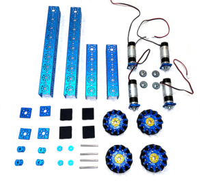
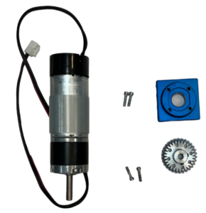
To complete this build, everything you need can be found in the FTC Drive Base Kit from Studica Robotics. Structure components include U-channel, end piece plates, and U-channel bumpers. Motion components include a gearmotor, orbital mount plates, tooth bevel gears, D-shaft, clamping shaft hub, D-shape collar clamp, and mecanum wheels. Screws, nuts, and spacers are also included. You can view all the materials needed here.
Drivetrain Build Instructions
This is a summary of the steps that need to be taken to build your Mecanum chassis. If you are looking for more detailed instructions with visual cues, click here. We've divided this build into three steps. First, we will walk you through the assembly of the frame, then prepare the gear motors and mecanum wheels. Once everything is prepared will assemble the drive base. You will find additional coding information below.
Step 1: Frame Assembly
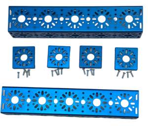
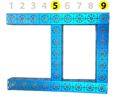
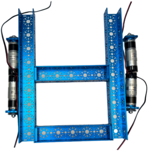
To start this drivetrain project you will assemble the structure components to build the basic frame. You will attach the end piece plates to the 240mm U-Channels with the socket head cap screws. Then you will attach the 240mm U-channel to the 432mm U-channels with the socket head cap screws. The 432mm U-channels have 9 hold patterns. The 240 mm U-channels should be placed at hole pattern #5 and #9 to connect the 432mm U-channel pieces. View detailed instructions.
Step 2: Preparing Motion Components
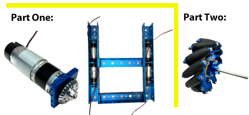
Part One: A. Screw the motors onto the orbital mount plate with the socket head cap screws.
B. Then attach one of the tooth bevel gears to the motor shaft and tighten. Then secure the orbital mount plate to the 432 mm U-channels with four socket head cap screws on each plate. The motors will recess in the 432mm U-channels.
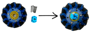
Part Two: Prepare the four mecanum wheels by screwing the clamp shaft hub to them using six socket head caps screws on each wheel.
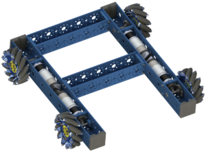
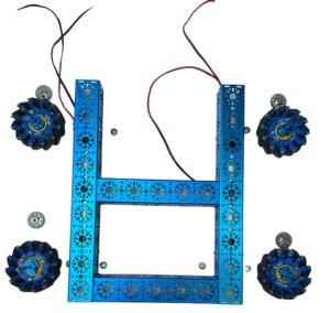
✔ This is how your items will look after these steps are completed.
Step 3: Final Assembly of Drivetrain
Now, let's put your drivetrain together! On the hole pattern that is adjacent to the bevel gear attached to the motor shaft, place the flange bearings onto the 432mm U-channel. Insert the D-shaft into the clamping shaft hub so that it is aligned with the shaft. Insert the shaft through the flange bearings and tooth bevel gear on the 432mm U-channel. Before you do anything else, make sure that the driving gear on the motor shaft and the driving gear on the wheel shaft mesh with each other. ✔ Check the teeth of the gears to see if they fit easily into each groove. This will allow them to turn effectively.
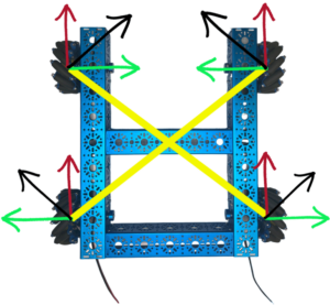
✔ Next, make sure your wheels are oriented as they are in the image to the right. Illustrated with yellow, you can see when you draw a line parallel to the angle of the rollers it creates an "X" shape. The force vectors are represented by the black arrows. You can add up the force vectors generated by the angle of the rollers to move in any direction. The red and green arrows represent the X and Y axes of movement that are made possible due to how the rollers are orientated in the build. Then simply place the D-shape collar clamp at the ends of the D-shaft and secure it by tightening the clamp with a screw.
Coding your Chassis
Here is the Onbot Java code that you will use for your drivetrain for use in FTC. Three variables are being used, (X, Y, and RX), that represent the three axes of movement of this mecanum drive base. The left stick will control the movement on the X and Y axis for forward, backward, and strafing from left to right motion. RX is the rotational movement variable. The denominator variable is the absolute value of the largest motor power or one. We want to keep the power ratio between -1 and 1. (View PDF for clearer coding instructions.) 
 In conclusion, we hope you enjoyed this mecanum drivetrain building guide. Again, if you'd like to work on this project, all the materials needed are included in the FTC Drive Base Kit from Studica Robotics. You can view our detailed building guide or a PDF of the instructions. Enjoy!


