Close
All Categories
    Filters
    Preferences
    Search

    HereFlow

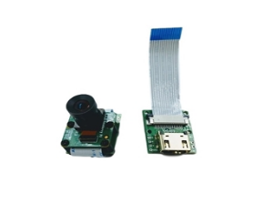
    Here Flow is a finger size optical flow sensor. Compared with other optical flow sensors, it is even smaller. It can be installed easily at any position without taking much space.


    A LiDAR component, an optical flow camera and a 6D IMU (ICM20602) are integrated in the Here FLOW.


    The LiDAR component is a power efficient high speed TOF range finder, which embeds the latest ST FlightSenseTM technology. In range of 2 m, it can acquire the distance within 5 ms. The accuracy is not affected by colour or reflection rate of the target surface.


    The Here Flow can be setup at any node in the CAN bus without noise problem.

    MFR Part #: 90200-HF
    Request a Quote
    Specification

    Size: 28.8mm*9.5mm

     
    Performance

     
    Hardware Specification

    1.  

      Built-in ultra small lidar module

    2.  

      CAN Protocol, which provide more reliable communication

    3.  

      Built-in IMU Module

    4.  

      PAW3903 Optical Flow Sensor. Effective ranges from 80 mm to infinity. *Old generation module used to have 3901

     
    Optical Flow Sensor Specification

    Type

    Parameter

    Range

    80 mm to infinity

    Field of view

    42 degree

    Maximum movement speed

    7.4 rad/s

    Minimum illumination

    >60 lux

    Infrared emitter

    940 nm invisible light emission (Class1)

    Operating temperature

    -20 to +70 °C

    Interface

    CAN

    Power supply

    5V

     
    Lidar Specification

    Type

    Parameter

    Measuring frequency

    Up to 50 Hz

    Field of view

    27 degree

    Longest distance

    2m

    Accuracy

    ±3 %

    Infrared emitter

    940 nm invisible light emission (Class1)

    Operating temperature

    -20 to +70 °C

    Interface

    CAN

    Power supply

    5V

     
    Installation

    Connect the CAN port on module and flight controller with the 4 Pin CAN cable. Point the Y axis of Here Flow to the nose of the aircraft. Face the camera to ground and stick the module to the bottom of aircraft by 3M sticker or soft sticker (with slightly vibration isolation).

    *DO NOT touch the electronic components on the PCB. Touch the edge of the PCB if possible during the installation.*

    *The bottom of module must be clear, otherwise the measured data will be affected.*

     
    Settings

    Firmware update instructions: https://discuss.cubepilot.org/t/can-flow-setup-instructions-alpha-batch/341

    1.Connect the flight controller to computer via USB cable. Open Mission Planner. Install the master firmware by "Load custom firmware". Go to "Full Parameter List" and find "CAN_P1_DRIVER". Change it to "1" to enable CAN.

    2.Find "RNGFND_TYPE" and set it to "24" to enable range finder. Set "RNGFND_MAX_CM" (maximum distance) to 200 cm; "RNGFND_MIN_CM" (minimum distance) to 5 cm.

    *Please note: We have integrated the TOF sensor in this component due to it being VERY useful for precision landing detection. However, it is NOT suitable for height detection in outdoor conditions above 0.5 m, nor is it suitable for indoor height estimations higher than 2 m.*

    *For accurate flow navigation, we still recommend installing the SF11B lidar from Lightware, or a similar Lidar that you trust.*


    Specification

    Size: 28.8mm*9.5mm

     
    Performance

     
    Hardware Specification

    1.  

      Built-in ultra small lidar module

    2.  

      CAN Protocol, which provide more reliable communication

    3.  

      Built-in IMU Module

    4.  

      PAW3903 Optical Flow Sensor. Effective ranges from 80 mm to infinity. *Old generation module used to have 3901

     
    Optical Flow Sensor Specification

    Type

    Parameter

    Range

    80 mm to infinity

    Field of view

    42 degree

    Maximum movement speed

    7.4 rad/s

    Minimum illumination

    >60 lux

    Infrared emitter

    940 nm invisible light emission (Class1)

    Operating temperature

    -20 to +70 °C

    Interface

    CAN

    Power supply

    5V

     
    Lidar Specification

    Type

    Parameter

    Measuring frequency

    Up to 50 Hz

    Field of view

    27 degree

    Longest distance

    2m

    Accuracy

    ±3 %

    Infrared emitter

    940 nm invisible light emission (Class1)

    Operating temperature

    -20 to +70 °C

    Interface

    CAN

    Power supply

    5V

     
    Installation

    Connect the CAN port on module and flight controller with the 4 Pin CAN cable. Point the Y axis of Here Flow to the nose of the aircraft. Face the camera to ground and stick the module to the bottom of aircraft by 3M sticker or soft sticker (with slightly vibration isolation).

    *DO NOT touch the electronic components on the PCB. Touch the edge of the PCB if possible during the installation.*

    *The bottom of module must be clear, otherwise the measured data will be affected.*

     
    Settings

    Firmware update instructions: https://discuss.cubepilot.org/t/can-flow-setup-instructions-alpha-batch/341

    1.Connect the flight controller to computer via USB cable. Open Mission Planner. Install the master firmware by "Load custom firmware". Go to "Full Parameter List" and find "CAN_P1_DRIVER". Change it to "1" to enable CAN.

    2.Find "RNGFND_TYPE" and set it to "24" to enable range finder. Set "RNGFND_MAX_CM" (maximum distance) to 200 cm; "RNGFND_MIN_CM" (minimum distance) to 5 cm.

    *Please note: We have integrated the TOF sensor in this component due to it being VERY useful for precision landing detection. However, it is NOT suitable for height detection in outdoor conditions above 0.5 m, nor is it suitable for indoor height estimations higher than 2 m.*

    *For accurate flow navigation, we still recommend installing the SF11B lidar from Lightware, or a similar Lidar that you trust.*
    Customers who bought this item also bought

    6mm Low Profile Hex Shaft Clamping Hub-V2

    #76296H
    $9.99

    The Studica Robotics 6mm Hex Shaft Low Profile Clamping Hub V2 is an ideal fit for our motors.

    Step File

    6mm Hex Shaft Face Bearing Block

    #76299H
    $10.89
    (In stock)

    The Studica Robotics 6mm Hex Shaft Face Bearing Block can be mounted on any channel and bracket allowing for a 6mm ID through hole for 6mm shafts (axles). The block has a permanently installed Standard Sealed Bearing and has 8 x M3 tapped through holes for easy mounting.

    WS500 Soldering Iron Kit

    #90200-SR
    Request a Quote

    Clamping 6mm Hex Shaft Hub-V2

    #76295H
    $7.99

    Precision Hub for Hex-Shaft Couplings

    The Studica Robotics 6 mm Low Profile Hex Shaft Clamping Hub V2 is engineered to deliver a secure and compact coupling between your motor or drive shaft and wheels, sprockets, or other mechanical components. With its 6 mm hex-shaft ID and low profile form, it's ideal for tight-space and high-precision builds.  Made of aluminum, the Studica Robotics Clamping 6mm Hex Shaft Hub-V2 is used with our wheels.


    Step File

    Rubber Grommet (10 pack)

    #76504-10
    $6.99
    (In stock)

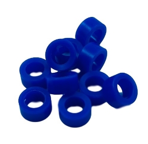
    Rubber Grommets are made for the Studica channel and plates and or any structure with a 14mm hole. Use it for protecting wire or as a bumper.

    Specifications:

    • Outside diameter: 18mm
    • Inside Diameter : 11mm
    • Hole fitting diameter: 14mm
    • Thickness: 9mm
    • Step File


    GT2-6mm Timing Belt Clamp w/Set Screw

    #76456
    $5.49
    ( 464 In stock)

    The GT2-6mm Timing Belt Clamp w/Set Screw is used with all the GT2 belts

    Specifications:

    6mm Hex Shaft Collar Clamp 2 Piece

    #76293H
    $4.39
    (In stock)

    The Studica Robotics 6mm Hex shaft collar clamp (2-piece) has a 6mm Hex hole and dimensions of 20mm x 8mm.

    EV SSL