Close
All Categories
    Filters
    Preferences
    Search

    myShake Earthquake Table

    The Studica Robotics Earthquake Shake Table is used in the STEM classroom to simulate the seismic shaking of structures, vibration research, stability/rigidity testing, resonant frequencies and sensor measurements.

    MFR Part #: 80002
    Request a Quote

    The Studica Robotics Earthquake Shake Table is used for data-driven design of safer buildings.  Students create their design of a building for earthquake resistance and conduct experiments to test building modifications.  Analysis of the data sets are used to develop a final design considering the building height, safety and associated costs. 

    Please note: The shake table can be used in conjunction with a NI myDAQ (or equivalent) and the former Pitsco myQuake circuit board or other similar instruments.  You can also bypass the myDAQ and circuit board with the utilization of a separate DC Motor, Barrel Connectors and a Video Analysis application (not included).

    Dimensions:  Top plate - 5.75" x 5", Bottom plate - 7.75" x 8", Height - 2.5"

    Tip: Using the Earthquake Shake Table to capture video footage and collect oscillation data

    Studica Shaker Table instructions image

    Items needed:

    1. A computer or iPad running video analysis software (not shown)
    2. Studica Earthquake Shaker Table with adapter pigtail (F, J)
    3. 12V-1250mA AC/DC power adapter (G)
    4. Female barrel connector (H)
    5. PWM Motor Controller (I)
    6. Sticky notes (not shown)
    7. Camera tripod (not shown)

    Key learning objectives and uses include the following:

    1. Earthquake Engineering Education:

      • Hands-On Learning: Educational institutions use earthquake simulation tables to provide students with hands-on experience in understanding the principles of earthquake engineering. This practical exposure helps students grasp complex concepts related to structural dynamics.

      • Experimentation: Students can conduct experiments on small-scale models to observe how various factors, such as building materials or structural configurations, impact a structure's response to seismic activity.

    2. Structural Testing and Research:

      • Material Response: Engineers use earthquake simulation tables to test how different materials and structures respond to seismic forces. This helps in designing buildings and infrastructure that can withstand earthquakes.

      • Structural Dynamics: Researchers study the dynamic behavior of structures under simulated earthquake conditions. This includes analyzing vibrations, deformations, and modes of failure to improve earthquake-resistant designs.

    3. Design Verification:

      • Prototyping: Engineers and architects use earthquake simulation tables during the prototyping phase of building design to verify the effectiveness of earthquake-resistant features before construction begins.

      • Innovative Solutions: Researchers and designers can experiment with new and innovative solutions to enhance seismic resilience in structures.

    4. Emergency Response Planning:

      • Scenario Testing: Emergency response agencies use earthquake simulation tables to simulate various seismic scenarios. This helps them plan and prepare for potential earthquake events, improving their response capabilities.

      • Evacuation Planning: Simulated earthquake scenarios allow city planners and emergency responders to evaluate and refine evacuation plans for areas prone to seismic activity.

    5. Equipment Testing:

      • Validation of Equipment: Critical equipment, such as medical devices or laboratory instruments, may need to be tested for their ability to function during and after an earthquake. Simulation tables provide a controlled environment for such testing.

      • Quality Assurance: Manufacturers of earthquake-resistant equipment use simulation tables to ensure that their products meet safety standards and can withstand seismic forces.

    Sample Video Analysis Instructions 

    Objective


    Capture and analyze the motion of a structure or object during a simulated earthquake using the Studica Robotics earthquake shake table and Vernier Video Analysis software. 
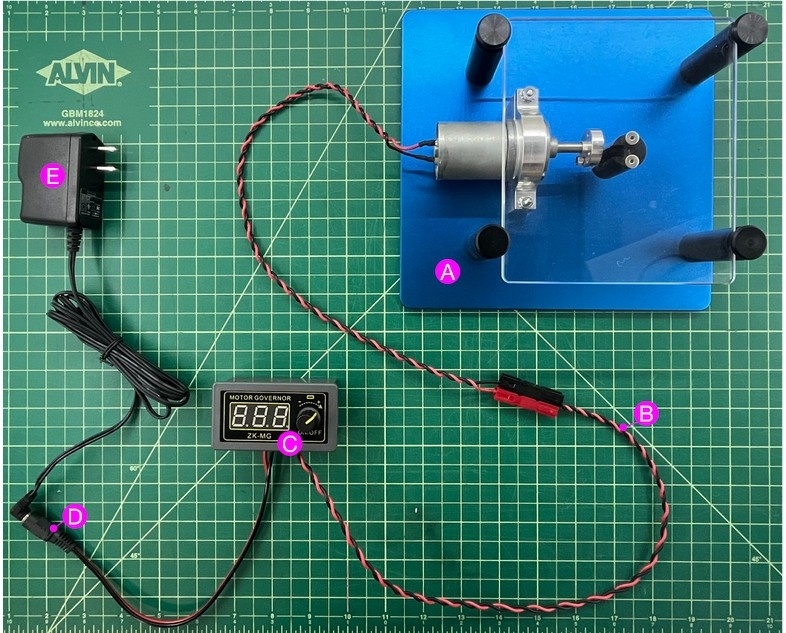
     

    Items Required:

    A. Studica Robotics Earthquake Shake table [Studica part #: 80002]

    B. Adapter pigtail (included with the Earthquake Shake table)

    C. Motor Speed Controlle

    D. Female barrel connector

    E. 12V–1250mA AC/DC power adapter (included with the Earthquake Shake table)

    F. Computer or mobile device running with video analysis software (not shown)

    G. Camera tripod if using mobile device (not shown – for stable video capture)

    H. Sticky notes (not shown – used as visual markers)

    Setup Instructions:

    1. Assemble the Electrical Components

    • Connect the 12V–1250mA AC/DC power adapter (E) to the female barrel connector (D).
    • Plug the female barrel connector (D) into the Motor Speed Controller (C) input port.
    • Connect the adapter pigtail (B) from the motor on the Studica shaker table to the output terminals of the Motor Speed Controller (C).
    • Use the PWM dial to control oscillation frequency. Gradually increase frequency to overcome stall.

    2.   Prepare the Shaker Table

    • Place the object or model structure onto the Studica Robotics Earthquake Shake table securely.
    • Affix sticky notes or high-contrast markers to parts of the object to serve as a target for tracking

    3.   Set Up the Camera

    • Mount your camera or device on a tripod, aligned perpendicularly to the plane of motion.
    • Ensure the entire table and the marker(s) are visible and in focus.
    • Consider using a plain, high-contrast background to aid video analysis.

    4.   Record the Motion

    • Turn on the shaker table using the PWM controller.
    • Record a 5–10 second video capturing the oscillations of the object.
    • Make sure the camera remains stationary during recording.


    Video Analysis Instructions:

    Using Vernier Video Analysis:

    1. Open the recorded video in the Vernier Video Analysis
    2. Set the scale using a known length (e.g., sticky note width or a ruler visible in the frame).
    3. Mark a point of interest (e.g., a sticky note on the top of the structure) for
    4. Collect position time data.
    5. Analyze oscillation frequency, amplitude, and damping effects as

    Safety Tips:

    • Do not run the shaker table continuously for more than a few minutes to prevent motor
    • Ensure all wires are properly connected and
    • Keep fingers and loose items away from moving parts during

    The Studica Robotics Earthquake Shake Table is used for data-driven design of safer buildings.  Students create their design of a building for earthquake resistance and conduct experiments to test building modifications.  Analysis of the data sets are used to develop a final design considering the building height, safety and associated costs. 

    Please note: The shake table can be used in conjunction with a NI myDAQ (or equivalent) and the former Pitsco myQuake circuit board or other similar instruments.  You can also bypass the myDAQ and circuit board with the utilization of a separate DC Motor, Barrel Connectors and a Video Analysis application (not included).

    Dimensions:  Top plate - 5.75" x 5", Bottom plate - 7.75" x 8", Height - 2.5"

    Tip: Using the Earthquake Shake Table to capture video footage and collect oscillation data

    Studica Shaker Table instructions image

    Items needed:

    1. A computer or iPad running video analysis software (not shown)
    2. Studica Earthquake Shaker Table with adapter pigtail (F, J)
    3. 12V-1250mA AC/DC power adapter (G)
    4. Female barrel connector (H)
    5. PWM Motor Controller (I)
    6. Sticky notes (not shown)
    7. Camera tripod (not shown)

    Key learning objectives and uses include the following:

    1. Earthquake Engineering Education:

      • Hands-On Learning: Educational institutions use earthquake simulation tables to provide students with hands-on experience in understanding the principles of earthquake engineering. This practical exposure helps students grasp complex concepts related to structural dynamics.

      • Experimentation: Students can conduct experiments on small-scale models to observe how various factors, such as building materials or structural configurations, impact a structure's response to seismic activity.

    2. Structural Testing and Research:

      • Material Response: Engineers use earthquake simulation tables to test how different materials and structures respond to seismic forces. This helps in designing buildings and infrastructure that can withstand earthquakes.

      • Structural Dynamics: Researchers study the dynamic behavior of structures under simulated earthquake conditions. This includes analyzing vibrations, deformations, and modes of failure to improve earthquake-resistant designs.

    3. Design Verification:

      • Prototyping: Engineers and architects use earthquake simulation tables during the prototyping phase of building design to verify the effectiveness of earthquake-resistant features before construction begins.
      • Innovative Solutions: Researchers and designers can experiment with new and innovative solutions to enhance seismic resilience in structures.

    4. Emergency Response Planning:

      • Scenario Testing: Emergency response agencies use earthquake simulation tables to simulate various seismic scenarios. This helps them plan and prepare for potential earthquake events, improving their response capabilities.

      • Evacuation Planning: Simulated earthquake scenarios allow city planners and emergency responders to evaluate and refine evacuation plans for areas prone to seismic activity.

    5. Equipment Testing:

      • Validation of Equipment: Critical equipment, such as medical devices or laboratory instruments, may need to be tested for their ability to function during and after an earthquake. Simulation tables provide a controlled environment for such testing.
      • Quality Assurance: Manufacturers of earthquake-resistant equipment use simulation tables to ensure that their products meet safety standards and can withstand seismic forces.

    Customers who bought this item also bought

    XT30 Male to JST-VH Cable

    #70180
    $4.99
    (In stock)

    The Studica Robotics XT30 Male to JST-VH cable is for use with the Servo Power Block (75006) and the FTC Power Block (70407).

    WS500 UAV Quadcopter Kit

    #90200
    Request a Quote

    The Studica WS500 UAV Quadcopter Kit is a lightweight robust UAV open platform specially designed for learning and teaching. It comes with the WS500 EDU Frame Kit and motors, ESCs, power frame integrated power distribution panel. It has a CubePilot flight controller with companion Raspberry Pi 5, an optical flow and distance sensor module with 6-axs IMU, a ToF (Time of Flight) 3D depth camera (with custom mount), and T-mini Plus lidar for obstacle avoidance and advanced navigation
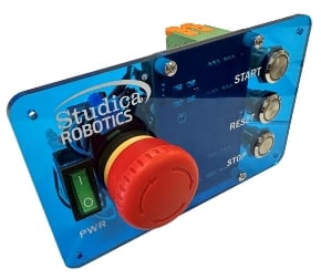
     

    All tools for installation are provided in box.


    Note: Battery not included. We recommend 4S 5200mAh + with XT60 Lipo Battery. You can purchase this in your local country.


    VMX2 Robotics Controller

    #70174
    Request a Quote

    This latest version of the VMX is the VMX2, a powerful robot controller,

    • Enables Tele-op and autonomous control
    • Programmable in Java, C++, Python, LabVIEW, and ROS
    • Integrates the navX-IMU, a Linux based controller, Gigabit Ethernet, USB3 ports and built-in Wifi/Bluetooth. 
    • Can be used in a Robot Control System or Vision/Motion processor
    • Supports Open CV, Tensor Flow, SLAM (Simultaneous Localization and Mapping 
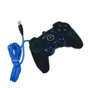
    • Step Files

    The VMX2 leverages five advanced key technology developments,

    • Highly-integrated, inexpensive, WiFi-enabled, multi-core Linux computing platform with lots of USB IO for expansion
    • 32-bit ARM Microcontrollers incorporating sophisticated I/O and digital communications engines
    • Low-cost MEMs Inertial Measurement Units (IMUs)
    • Powerful software providing rich libraries and tools for developing robot software in C++, Java
    • CAN bus for high-speed, real-time communication between devices

    The Studica VMX2 Technology Enables,

    • Far richer development environments and tools
      • Because VMX2 is much more than a robot controller – it is a powerful, Linux-based desktop computing platform with network/monitor/keyboard/mouse support.
    • Very powerful software features
      • State-of-the-art software development GUIs (e.g., VS Code) libraries and tools (drive-  train kinematics, path-planning, vision processing, autonomous navigation,   performance data acquisition/playback)
    • Access to cutting-edge sensors (for use outside the competition)
      • VMX’s multitude of modern digital communications interfaces and Linux-based   operating system allow users to directly access most modern devices (e.g., Intel   RealSense tracking and depth cameras and LIDAR

    Servo Power Block

    #75006
    $36.99
    (In stock)

    The Servo Power Block is a 6V, 60W power injector that provides proper power for RC Servos. It does not interfere with the signal, it will only replace the power to the servo with 6V. 

    Features,

    • Built in DC-DC converter
    • Over-current shutdown
    • ESD protection

    Specifications,

    • Nominal Input Voltage: 12V
    • Operational Voltage Range: 6.0V
    • Number of Channels: 8
    • Max Current for All Channels Combined: 10A
    • Total Continuous Power: 60W
    • Size: 70mm x 45mm x 16mm
    • Step File


    PWM cable Set - TJC8 3 pin - 22AWG - F-F - 12 pcs

    #71011
    $17.49
    ( 477 In stock)

    This set of 12 pieces includes,

    • 2 x 20cm 22AWG Cables with Dupont TJC8 2.54mm 3 pin, female to female connectors
    • 2 x 40cm 22AWG Cables with Dupont TJC8 2.54mm 3 pin, female to female connectors
    • 2 x 60cm 22AWG Cables with Dupont TJC8 2.54mm 3 pin, female to female connectors
    • 6 x 3pin Dupont male to male connectors

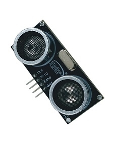
    Ultrasonic Distance Sensor

    #70753
    $19.99
    ( 19 In stock)
    • Stable, accurate distance measurement
    • High precision, blind spots (3cm) super close
    • A full set of ranging process
    • Step File

    Titan Cable Pack

    #70162
    $6.99
    ( 493 In stock)

    The Titan Cable Pack contains three cables. A 60cm CAN Wire for connecting the Titan Motor Controller to a CAN 2.0B capable device and two (idk the 50cm JST-VH to JST-VH cables for connecting 12VDC power to other devices such as the VMX or Servo Power Block.

    • 2 - JST-VH to JST-VH cable
      • 50cm
    • 1 - CAN Wire
      • 60cm


    EV SSL