| 1 |
High Current Power Input |
Primary High Current Power Input |
Use either of the power inputs; all are tied in parallel. Connector can support up to 60A. |
| 2 |
Secondary Power Input |
Lower Current Power Input |
Use either of the power inputs; all are tied in parallel. Connector can support up to 45A. |
| 3 |
Power Switch Input |
Power switch cables route here to turn the panel on and off |
This is the main power switch for the entire robot. |
| 4 |
Cooling Fan |
Keeps the heatsink cool |
Fan is 12V, if using 24V a fan replacement is required. |
| 5 |
E-Stop |
Controls power to the high current output |
Hitting the E-Stop will only turn off power to the high current output. Controller and Light Tower power will remain. |
| 6 |
Power Switch |
Power switch for the entire robot |
Power no longer flows through the switch and instead the switch is used as a gate control. |
| 7 |
E-Stop Input |
Where the E-Stop wires route to |
E-Stop port for the wires coming from the E-Stop. |
| 8 |
Controller and Light Tower Output Power |
Output power to the Light Tower and Controller |
This power stays on when E-Stop is pushed. Only way to turn off is with main power switch. |
| 9 |
High Current Power Output |
Primary High Current Power Output |
Provides output power to the rest of the robot. Suggested to be wired direct to the High Current Power Distribution Board. |
| 10 |
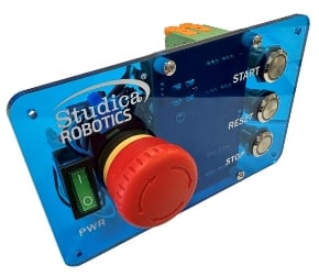
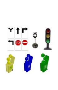
Stop Button |
A button that can be used by the user |
Provides a Red LED and NO / NC Momentary interface. |
| 11 |
Reset Button |
A button that can be used by the user |
Provides a Yellow LED and NO / NC Momentary interface. |
| 12 |
Start Button |
A button that can be used by the user |
Provides a Green LED and NO / NC Momentary interface. |