










FTC Odometry: Getting Started with the Cypher MAX Encoder
Quick Summary: The Cypher MAX is an external encoder that can help FTC teams track robot movement for odometry and localization. Learn how external encoders and dead wheels work, why they can improve autonomous movement, and the basics of quadrature and absolute encoders.
FTC Odometry: Know Where Your Robot Is
In autonomous, knowing where your robot should be isn't enough. You need to know where it actually is. FTC odometry uses sensor data to estimate your robot's position and movement on the field, helping teams create autonomous routines that are more precise and repeatable.
 Many FTC teams use the encoders built into their drive motors to estimate movement. But when wheels slip, traction changes, or a mecanum drivetrain strafes across the field, motor rotation doesn't always tell the whole story. An external encoder and tracking wheel can provide another way to measure how the robot is actually moving.
The Cypher MAX Through Bore Encoder is an external through-bore encoder that can be used with a dead wheel for odometry and robot localization, as well as applications such as mechanism position tracking and RPM measurement. Let's look at how it works and why external encoder data can be useful for FTC teams.
What Is an Encoder?
An encoder is a sensor that measures rotational movement. As a shaft or wheel rotates, the encoder converts that movement into signals that a robot controller can use to determine position, speed, distance, or direction. This information is especially valuable for autonomous routines that require precise and repeatable movement.
How Is the Cypher MAX Different from a Typical Motor Encoder?
A typical motor encoder measures the rotation of the motor shaft. The Cypher MAX is an external through-bore encoder, which means it can be mounted independently from the drive motor.
For example, an FTC team can mount the Cypher MAX to a dedicated tracking wheel, commonly called a dead wheel, to measure the actual movement of the robot rather than relying only on drivetrain motor rotation. This gives teams another source of encoder data for odometry and robot localization.
Why Use an External Encoder for FTC Odometry?
Using motor encoders to estimate drivetrain movement is a straightforward approach to localization, and it can work well. However, the rotation of a drivetrain wheel does not always perfectly represent the robot's actual movement.
This is particularly relevant for mecanum-drive robots. When a robot accelerates, decelerates, strafes, or rotates, changes in traction can cause drivetrain wheels to slip or lose contact with the field. The motor encoder continues to measure the rotation of the motor shaft, even when the robot's actual movement differs from the calculated movement.
That difference can become more noticeable when an autonomous routine needs to make precise strafing movements, navigate to multiple locations, align with field elements, or position the robot consistently for scoring. An external encoder mounted to a dedicated tracking wheel provides another way to collect movement data that is less dependent on drivetrain motor rotation.
What Is a Dead Wheel?
 A dead wheel, also called a tracking wheel, is a small unpowered wheel dedicated to measuring robot movement. The wheel and encoder are often mounted together as part of an odometry pod.
Unlike a drivetrain wheel, a dead wheel does not drive the robot. Instead, it rolls along the field as the robot moves. An encoder attached to the wheel measures its rotation, providing data that can be used to estimate the robot's movement and position.
Many odometry systems use multiple tracking wheels positioned to measure movement in different directions. By combining these encoder measurements with the known positions of the tracking wheels on the robot, software can estimate forward movement, lateral movement, and changes in heading.
Dead wheels are not completely immune to error. They can still slip or lose contact with the field if the odometry pod is poorly designed.
Dead Wheel Reliability Checklist
A dead wheel can provide useful odometry data, but the mechanical setup matters. Before relying on a tracking wheel for autonomous movement, check that your odometry system is set up to provide consistent readings.
Use this checklist when designing or troubleshooting your dead wheel setup:
- Maintain consistent contact with the field. The tracking wheel should stay in contact with the field as the robot moves without excessive bouncing or losing contact.
- Minimize mechanical flex. Movement in the odometry pod or mounting structure can introduce inaccuracies into your encoder readings.
- Properly support the encoder. Make sure the encoder and shaft are securely mounted to prevent unnecessary movement or misalignment.
- Keep the tracking wheel aligned. Proper alignment helps ensure the wheel is measuring movement in the intended direction.
- Reduce unnecessary vibration. Excessive vibration or movement in the mechanism can affect the consistency of your measurements.
Remember: Dead wheels are not completely immune to error. Wheel slip, inconsistent field contact, mechanical flex, and setup issues can still affect localization accuracy.
Benefits of External Encoders for FTC Teams
Using an external encoder with a dead wheel gives FTC teams another source of movement data that is less dependent on drivetrain motor rotation. This can help reduce the effects of drivetrain wheel slip on localization and support more precise and repeatable autonomous movements.
External encoders also give students an opportunity to explore how encoder data is used for odometry and robot localization, while creating a foundation for more advanced autonomous programming.
What Is the Difference Between a Quadrature Encoder and an Absolute Encoder?
Encoders can measure rotation in different ways. Two common types are quadrature encoders and absolute encoders, and the difference comes down to how they report position.
A quadrature encoder tracks changes in position as a shaft rotates. It outputs signals through its A and B channels, and the robot can interpret those signals to determine how far and in which direction the shaft has moved. The Cypher MAX also includes an index, or I, channel that provides a reference point once per revolution.
An absolute encoder works differently. It provides a position value that corresponds to the shaft's current position, rather than requiring the robot to track changes from a starting point. The position is represented by a unique output value, allowing the robot to determine the shaft's position without calculating movement from a starting point.
| Feature | Quadrature Encoder | Absolute Encoder |
| What it measures | Changes in position as the shaft rotates | The shaft's current position |
| How position is determined | Counts pulses from movement starting from a reference point | Each shaft position has a unique value |
| Direction | A and B channel timing can be used to determine direction | Direction can be determined by comparing position readings |
| Channels / Output | A, B, and I (index) channels | Absolute PWM output |
| Resolution | 2,048 counts per revolution | 12-bit resolution |
| Reference point | I/index channel provides one reference point per revolution | No need to count from a starting position |
| Best for | Tracking movement, distance, and rotation | Knowing the shaft's current position |
Why Does This Matter for FTC Teams?
For odometry, teams are primarily interested in measuring how much movement has occurred, which is where quadrature encoder data is useful. The robot can count encoder changes and combine that information with factors such as wheel circumference, gear ratios, and tracking wheel placement to estimate movement across the field.
Absolute position data can be useful in other situations, particularly when a robot needs to know the current position of a rotating mechanism or shaft.
The Cypher MAX provides A, B, and I quadrature outputs as well as an absolute PWM output, giving teams flexibility for odometry, mechanism position tracking, and other robotics applications.
Applications for the Cypher MAX Encoder
Odometry and robot localization are just some of the potential applications for an external encoder.
The Cypher MAX can also be used for:
- Mechanism position tracking
- Arms and lifts
- Rotating or pivoting mechanisms
- RPM measurement
- General shaft position tracking
This makes an external encoder a useful tool not only for autonomous navigation but also for teaching and experimenting with different robotics applications.
Getting Started with Hardware and Software Setup
Once you understand how the encoder works, the next step is installing it and configuring your robot to read its data.
Setup at a Glance
| Component | What It Does |
| Cypher MAX Encoder | Measures rotational movement and provides quadrature or absolute position data |
| FTC cable | Connects the encoder to compatible FTC hardware |
| Tracking wheel or mechanism | Converts movement into encoder rotation for measurement |
| Shaft or insert | Connects the encoder to the mechanism being measured |
| Mounting hardware | Keeps the encoder and tracking mechanism securely positioned |
Hardware Installation
When mounting an encoder for odometry, focus on keeping the encoder properly supported, aligned, and protected from unnecessary movement or flex.
For an odometry pod, the tracking wheel should maintain consistent contact with the field while still rotating freely. A stable mechanical setup helps produce more consistent encoder readings and, ultimately, more reliable position tracking.
Example Odometry Pod
 |
 |
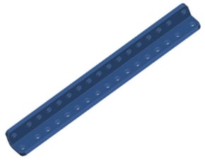
Above is an example of a simple odometry pod system. The encoder is angled so that the omni-wheel can maintain contact with the ground, while also simultaneously being housed safely. The hole pattern on the U-Channel allows for adjusting the angle of the encoder tracking wheel accordingly to ensure contact with the ground.
Odometry Example Build
 |
 |
This is one example of how an odometry pod can be integrated into a mecanum drivebase. The encoders are mounted on the inside of the robot's frame to protect the encoders as well as to accurate track the robot's movement about it's center of mass. Teams can modify the design to fit their own robot while keeping the same basic design principles in mind.
Software Setup
Once the hardware is installed, the general configuration process is:
- Connect the encoder to compatible FTC control hardware.
- Open the robot's hardware configuration.
- Verify that the connected hardware is recognized.
- Identify the ports being used for the external encoders.
- Give the encoders appropriate names, such as
encoderXandencoderY. - Read the encoder values in your robot code.
- Convert encoder counts into useful movement or position data.
The exact setup will depend on the FTC hardware and software configuration being used.
Software Setup Instructions
In the configuration file, declare an unspecified motor in the port being used, and give it a name such as "cypherMax". External quadrature encoders are accessed through the corresponding motor object.

Declaring Encoder in Configuration File Cypher MAX being declared in the configuration file. Here is the example code to set up the encoder.

Setting up Encoder: At the beginning of the OpMode, reset the encoder and establish the starting encoder position as 0. Create the variables.

Creating Variables Create the following variables:
- encoderCounts
- revolutions
- distanceMM
- distancesInches
Then establish constraints.

Establish Constants Establish constants for the encoder and wheel specifications and calculate the tracking wheel's circumference.
Read the encoder.

Reading the Encoder When the OpMode begins, it will continuously read the encoders current position, then calculate the amount of revolutions. Then calculate distance.

Calculating Distance Traveled After calculating how many revolutions the tracking wheel performs, the OpMode uses the that calculation to determine how far the robot has traveled from it's starting position in millimeters and inches. Then add telemetry.

Adding Telemetry Data All the data calculated then gets displayed on the driver hub.
Here is the complete code.

Frequently Asked Questions
What is FTC odometry?
FTC odometry is the process of using sensor data, such as encoder measurements, to estimate a robot's position and movement on the field.
What is a dead wheel in FTC robotics?
A dead wheel is an unpowered wheel dedicated to measuring robot movement. As the robot moves, the wheel rotates and an encoder measures that rotation.
Why use an external encoder instead of a motor encoder?
Motor encoders measure motor rotation, which may not always perfectly represent the robot's actual movement if the drivetrain wheels slip. An external encoder connected to a tracking wheel provides another source of movement data.
What is the difference between a quadrature and absolute encoder?
A quadrature encoder measures changes in position by generating pulses as the shaft rotates. An absolute encoder provides information about the shaft's current position.
How many counts per revolution does the Cypher MAX have?
The Cypher MAX provides 2048 counts per revolution in quadrature mode.
Can the Cypher MAX be used for applications besides odometry?
Yes. External encoders can also be used for mechanism position tracking, arms, lifts, rotating mechanisms, and RPM measurement.
Do dead wheels eliminate all localization errors?
No. Dead wheels can still experience errors from slip, inconsistent contact with the field, mechanical flex, or incorrect software configuration.
What is the difference between a dead wheel and a motor encoder?
A motor encoder measures the rotation of a motor, while a dead wheel uses an unpowered tracking wheel and encoder to measure the robot's movement independently of the drivetrain.
Take Your Odometry Further
Understanding how a robot moves is an important part of building reliable autonomous routines. External encoders and dead wheels give FTC teams another way to collect movement data and explore robot localization beyond the encoders built into their drive motors.
The Cypher MAX provides a versatile external encoder option for FTC odometry, mechanism tracking, and other robotics applications. Whether your team is just learning about robot localization or working toward more precise autonomous routines, understanding encoder data is a valuable step in developing better-performing robots. Related Articles: